When will my CAD file be quality tested by PLAN SUBMISSIONS ONLINE?
When the PLAN SUBMISSIONS ONLINE user invokes the “Validate” button, the uploaded CAD file will be quality tested by the PLAN SUBMISSIONS ONLINE application. Note: this function is not available when an optional CAD file is uploaded for a plan purpose that does not require a CAD file, no checks will be run, and the map check is not required.
How long will the “Validate” take?
The “Validate” operation may take several minutes. The PLAN SUBMISSIONS ONLINE user does not have to stay logged on to PLAN SUBMISSIONS ONLINE for this process to complete. While the checks are running, the user can move on to the next steps and visit the map, add supporting documents, or log off and return later to review the results.
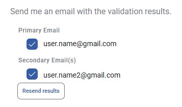
An email of the results can also be sent when the checks are complete. For each email address selected, the results will be sent upon successful validation. After validation, the results may be resent using the “Resend results” button when available.
The “Validate/Continue” button will not activate. What should I do?
Ensure that the Plan Type, Plan Purpose and Survey Date are populated and the “Validate/Continue” button will activate.
Are there any CAD file standards that need to be followed to submit a CAD file to PLAN SUBMISSIONS ONLINE?
Yes. The general CAD file requirements are:
- CAD submissions must be in AutoCAD dwg format. No other formats will be accepted.
- Individual files are required for each submission. i.e., two subdivisions cannot be submitted on one digital CAD submission.
- All CAD file submissions must be accompanied by a PDF or TIFF file derived from the dwg file. This image file must be a replica of the CAD file and will be the official plan of record once approved.
- CAD file data must be segregated according to the CAD Layer Chart found in the Saskatchewan CAD File & Georeferencing Specifications. CAD data that does not have a layer defined in the CAD Layer Chart must be drafted on other non-ISC layers. (Appendix A contains illustrations of CAD layers)
- CAD files must be georeferenced in accordance with the Saskatchewan CAD File & Georeferencing Specifications.
- Line work must be topologically clean; without duplicates (on the same layer), gaps and overshoots.
- The plan body must be drawn in Model space.
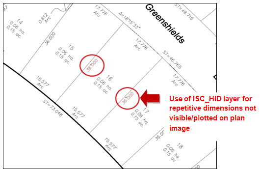
- Dimensions and angles not shown on the plan body due to limited space should be placed on the layer ISC_HID (not plotted on plan image).
- Leader lines must be kept to a minimum and used only where necessary.
- An area of at least 20mm but no more than 40mm in width around all edges of a plan shall be kept clear of any information. All plans must have a border.
What CAD layer do I put my details on?
If the survey plan details are created using AutoCAD’s viewport functionality, whereby the plan body line work and dimensions are merely viewed at a different scale, then it is appropriate to keep the detail line work and dimensions on the source ISC layers. If details are created by coping and scaling data from the plan body, then the detail should be drawn on any non ISC_ layer of your choice.
Where should I put anything not specified in the Layer Standards?
Information not pertaining to layers specified in the Saskatchewan CAD File & Georeferencing Specification can go on any non ISC_ layer of your choice.
Where should I put my Lot and Block numbers?
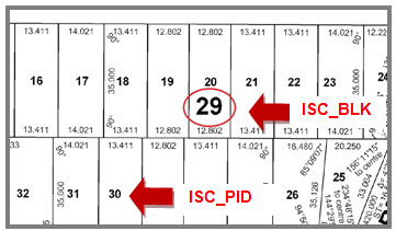
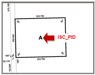
ISC_PID is reserved for parcel centroids which in a subdivision would typically be the lot numbers. ISC_BLK is reserved for Block number when lot numbers exist as in figure below. ISC_PID should be used for the parcel numbers in situations where there is no lot as in second figure below:
What elements should I put on layer ISC_STR?
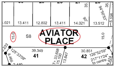
Street names and street or lane widths inside of the area of interest should be drafted on ISC_STR as illustrated below.
Do I need specific named block for the monuments on layer ISC_MON?
Yes, The block names should be as follows:
| Block Name |
Symbol |
Description |
| FIP |
 |
Found Iron Post |
| PLIP |
 |
Planted Iron Post |
| SCM |
 |
Survey Control Marker |
| RP |
 |
Reference Point* |
These rules allow automatic extraction of extended plan properties corner locations.
Users have the option of editing the extracted corner information manually to correct any erroneous information. For example, a secondary monument may exist on a plan within close proximity of a primary corner; in this case, PLAN SUBMISSIONS ONLINE may extract both monuments; if this occurs, the user can delete the appropriate corner. Users also have the ability to manually add corners.
What are the georeferencing requirements?
Refer to the Saskatchewan CAD File & Georeferencing Specifications for details.
How do I resolve a Structure Check error?
The structure check tests that data is present on the layers required for the plan purpose selected. The details of the layers required for each plan purpose are detailed in this table:
| Plan Purpose |
Fail |
Warning |
| Condo Bareland |
ISC_TBK, ISC_LEG, ISC_NAR, ISC_APP, ISC_PID, ISC_PCL, ISC_MON, ISC_DIM, ISC_OUT |
ISC_RWD |
| Condo Combo |
ISC_TBK, ISC_LEG, ISC_NAR, ISC_APP, ISC_PCL, ISC_MON, ISC_DIM, ISC_OUT |
ISC_RWD |
| Condo Normal |
ISC_TBK, ISC_LEG, ISC_NAR, ISC_APP, ISC_PCL, ISC_MON, ISC_DIM, ISC_OUT |
ISC_RWD |
| Consolidation – Graphical |
ISC_TBK, ISC_LEG, ISC_NAR, ISC_APP, ISC_MON, ISC_OUT, ISC_PID |
ISC_KEY, ISC_BLK, ISC_STR, ISC_RWD |
| Highway ROW |
ISC_TBK, ISC_LEG, ISC_NAR, ISC_APP, ISC_PID, ISC_PCL, ISC_MON, ISC_DIM,ISC_OUT, ISC_AREA |
ISC_RWD |
| Mineral Consolidation – Graphical |
ISC_TBK, ISC_LEG, ISC_NAR, ISC_APP, ISC_PID, ISC_MON, ISC_OUT |
ISC_BLK, ISC_RWD |
| Mineral Disposition |
ISC_TBK, ISC_LEG, ISC_NAR, ISC_APP, ISC_PCL, ISC_MON, ISC_DIM, ISC_OUT, ISC_PID |
ISC_KEY, ISC_RWD |
| Mineral Subdivision - Graphical |
ISC_TBK, ISC_LEG, ISC_NAR, ISC_APP, ISC_PID, ISC_MON, ISC_OUT |
ISC_KEY, ISC_RWD, ISC_DIM, ISC_PCL |
| Munic. Expropriation |
ISC_TBK, ISC_LEG, ISC_NAR, ISC_APP, ISC_PID, ISC_PCL, ISC_MON, ISC_DIM,ISC_OUT, ISC_AREA |
ISC_RWD |
| Municipal Road |
ISC_TBK, ISC_LEG, ISC_NAR, ISC_APP, ISC_PID, ISC_PCL, ISC_MON, ISC_DIM,ISC_OUT, ISC_AREA |
ISC_RWD |
| Par Class Code Chg - Graphical |
ISC_TBK, ISC_LEG, ISC_NAR, ISC_APP, ISC_PID, ISC_MON, ISC_OUT |
ISC_INT, ISC_STR, ISC_RWD |
| Prov Boundary Sur |
ISC_TBK, ISC_LEG, ISC_NAR, ISC_MON |
ISC_RWD |
| Public Improvement |
ISC_TBK, ISC_LEG, ISC_NAR, ISC_APP, ISC_PCL, ISC_PID, ISC_MON, ISC_OUT, ISC_DIM ISC_AREA |
ISC_RWD |
| Railway |
ISC_TBK, ISC_LEG, ISC_NAR, ISC_APP, ISC_PID, ISC_PCL, ISC_MON, ISC_DIM, ISC_OUT |
ISC_KEY,ISC_RWD |
| Reference Survey |
ISC_TBK, ISC_LEG, ISC_NAR, ISC_MON |
ISC_RWD |
| Replot |
ISC_TBK, ISC_LEG, ISC_NAR, ISC_APP, ISC_MON, ISC_OUT, ISC_PID, ISC_PCL, ISC_DIM |
ISC_KEY, ISC_INT, ISC_STR, ISC_BLK, ISC_RWD |
| Res Re-establishment |
ISC_TBK, ISC_LEG, ISC_NAR, ISC_MON |
ISC_RWD |
| Right of Way |
ISC_TBK, ISC_LEG, ISC_NAR, ISC_APP, ISC_RW, ISC_AREA, ISC_MON, ISC_DIM, ISC_OUT |
ISC_KEY, ISC_RWD |
| RM Roadway |
ISC_TBK, ISC_LEG, ISC_NAR, ISC_APP, ISC_PID, ISC_PCL, ISC_AREA, ISC_MON, ISC_DIM, ISC_OUT |
ISC_RWD |
| Road Easements |
ISC_TBK, ISC_LEG, ISC_NAR, ISC_APP, ISC_RW, ISC_AREA, ISC_MON, ISC_DIM, ISC_OUT |
ISC_RWD |
| St or Lane Opening |
ISC_TBK, ISC_LEG, ISC_NAR, ISC_APP, ISC_MON, ISC_OUT, ISC_PID, ISC_PCL, ISC_DIM |
ISC_KEY, ISC_RWD, ISC_STR |
| Subdivision |
ISC_TBK, ISC_LEG, ISC_NAR, ISC_APP, ISC_PID, ISC_PCL, ISC_MON, ISC_DIM, ISC_OUT |
ISC_KEY, ISC_INT, ISC_STR, ISC_BLK, ISC_RWD |
| Surface Lease |
ISC_TBK, ISC_LEG,ISC_NAR, ISC_APP, ISC_PCL, ISC_MON, ISC_OUT, ISC_PID, ISC_DIM |
ISC_KEY, ISC_RWD, ISC_BLK |
| Township Plat |
ISC_TBK, ISC_LEG, ISC_NAR, ISC_APP,ISC_MON,ISC_OUT, ISC_PID |
ISC_RWD |
| Utility Easement |
ISC_TBK, ISC_LEG, ISC_NAR, ISC_APP, ISC_MON, ISC_OUT |
ISC_KEY, ISC_RWD, ISC_DIM |
| Water Lots |
ISC_TBK, ISC_LEG, ISC_NAR, ISC_APP, ISC_PCL, ISC_PID, ISC_MON,ISC_OUT, ISC_DIM |
ISC_KEY, ISC_BLK, ISC_RWD |
How do I resolve a Scale Check error or warning?
Allowable scales are 10000, 5000, 2000, 1000, 500, 200, 100. The Controller of Surveys can approve the use of non-standard scales if requested. In this situation, the user can acknowledge the warning.
The scale text cannot be part of a block.
How do I resolve a North Check error?
Make sure a north arrow exists on layer ISC_NAR in your CAD file and on your plan image.
How do I resolve an Approval Line Check error?
Make sure an approval line exists on layer ISC_APP in your CAD file and on your plan image.
How do I resolve a Key Plan Check warning?
If your plan does not require a Key Plan, acknowledge the warning.
How do I resolve a Province Check error?
Saskatchewan spelled correctly in full must be on layer ISC_TBK and plan image. “Sask.” is not an acceptable short form.
How do I resolve a Map Border and Plot Size Check error?
Please check the following conditions when submitting plan images. Survey plan images must have a map border.
Map border space (based on 300 DPI file): 20mm to 40mm
Plot Size Maximum (based on 300 DPI file): 860mm by 3000mm
The map border and plot size tests are performed on the Survey plan image.
How do I resolve a Radial Lines error?
Please check that radial lines are on ISC_RDL and that they exist at the beginning and end of all curves within the area of interest.
How do I resolve a Perpendicular Widths Check warning?
Perpendicular street widths on ISC_STR need to be shown twice for all roads, streets and lanes within the approval area. If a width is shown only once, not making a pair, this will flag an error.
How do I resolve a Legend Check error?
Make sure the legend information is on layer ISC_LEG. View the error or warning details to determine which statements are missing from the legend. For more information regarding standard legend content, see Appendix E: Plan Legend Standards in the Saskatchewan CAD File & Georeferencing Specifications.
How do I resolve a Parcel Topology Check error?
Parcel Topology checks for dangles on layers ISC_PCL and ISC_INT or ISC_RW when applicable for the plan purpose. The error details will provide an XY coordinate of the dangle.
Do I need to create polygons for layer ISC_PCL?
No – creating polygons are not required or suggested.
Is there a snapping or cleaning tolerance used in the Parcel Topology Check?
Yes – a tolerance of 0.05m is used. Only gaps and dangles beyond this tolerance will be flagged to the user.
How does the Dimension Checker work?
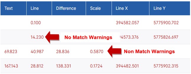
The Dimension Checker works by selecting lines and arcs on particular layers based on plan purpose and comparing the geometry to the annotative text on layer ISC_DIM within a reasonable proximity. The matches (where the measured distance of the line or arc geometry equals the annotative text) are reported to the user in black. Where there appears to be a non-match condition (differences beyond scale range of 0.9992 to 1.0008), the results are reported as warnings in red. Scale is derived by dividing line length by the annotative text value. Using the scale value to flag warnings accounts for plans mapped in GRID.
When no relevant text is found near the line or arc, this condition is reported back as a warning in red and no value is in the text column. Warnings can be toggled, and results sorted by the column headings.
This tool is useful to verify any suspected differences between the drafted length and the annotated length. Line X and Line Y coordinates provide the user with a means to locate the suspect geometry within their CAD file.
How does the Dimension Checker address dimensions crossing the road allowances?
It is not uncommon for dimensions to indicate a distance across a road allowance which when compared, would not match the line work length. These situations are accounted for by the dimension checker and not marked as warnings.
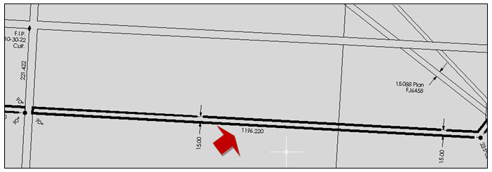
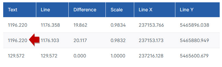
Dimensions results that differ between the annotative text and the line or arc geometry by approximately 20.12 are consider as matches. This eliminates the need to review these situations.
How does the Angle Checker work?
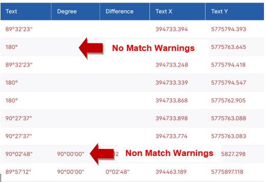
The Angle Checker works by selecting all the annotative text on layer ISC_DIM that is formatted as an angle (i.e. Degrees, Minutes, Seconds) and compares the value to the angles formed by lines on particular layers based on plan purpose and within a reasonable proximity. The matches are reported on the user interface in black. Where there appears to be a “non-match condition” (differences of 4 seconds or greater) the results are reported as warnings in red.
When no angle created by line work is found near the annotative angle text, this “no match” condition is reported back as a warning in red, and no value is in the “Degree” column. Warnings can be toggled, and results sorted by the column headings.
This tool is useful to identify any suspected differences between the measured angle and the annotated angle. Angle text X, Y coordinates provide the user with a means to locate the suspect angle within their CAD file.
 What are the Angle and Dimension Checker restrictions?
There will undoubtedly be situations where “no match” and “non-match” conditions are flagged as warnings, and upon user review, they will be deemed as correct. This is essentially due to the numerous variations that can occur in a drafted CAD plan. In particular, the use of lead lines affects the results. Details and repetitive dimensions also affect the results. The CAD layer ISC_HID can be utilized to assist in limiting the number of “no match” conditions.
The user can acknowledge the warnings and continue with the request process.
 Does the Angle Checker check angles against previous plans?
No
How do I resolve a Georeference Check error?
Georeference check requires that blocks named “RP” are used on layer ISC_MON to define reference points. The XY coordinates must be stated on layer ISC_LEG in the legend or on layer ISC_HID if you wish to hide the values from the plan of record. The georeference check will verify that RP1 in the CAD drawing is spatially located at the coordinates stated. Each XY coordinates should be on a single line, Northing followed by Easting, as illustrated below.
RP1: Northing 5697447.150; Easting 616303.220
RP2: Northing 5696643.720; Easting 616322.062